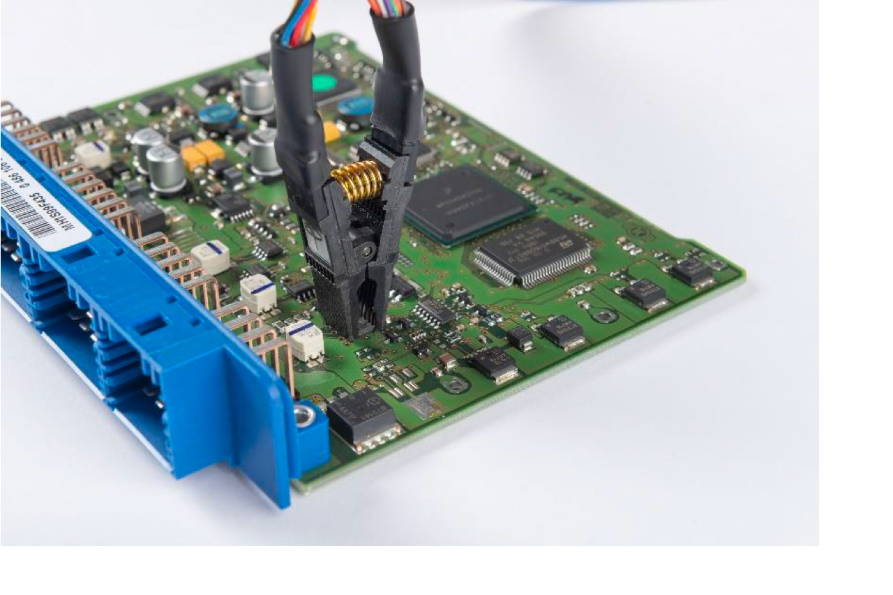
The new GRS200 fault locator uses the proven passive analogue signature analysis and compares a faultless assembly with the board under test. This method detects typical faults in electronics production, service and repairs quickly and without extensive circuit knowledge.
‘By using the GRS200, missing or reversed components, incorrect component values or component types, counterfeit components as well as short circuits or opens can be recognized very easily,’ says Hermann Reischer, Managing Director of Polar Instruments GmbH. The system consists of analogue signature hardware and powerful software with LIVE signature analysis, program mode and CAD data display. In addition, circuit diagrams, assembly photos, repair reports and an optional digital multimeter may be integrated. For detailed analysis, the system imports more than 20 different formats CAD data, including GenCAD, Hyperlynx, IPC-2581 and ODB++. Furthermore, circuit networks can be graphically highlighted and the associated components displayed.
The nodal impedance test is performed on the unpowered module, whereby a current-limited AC voltage signal generates an impedance signature by measuring voltage and current. The GRS200 system compares the signatures of the defective module with a stored good sample and indicates any noticeable deviations above a defined limit value. As an alternative to the nodal impedance test, an external multimeter can also be integrated into the test process. This allows, for example, voltage and resistance values, frequencies and temperatures to be assigned to defined test points in the CAD layout. It is also possible to locate short circuits on power supply rails and bus lines. An integrated short-circuit locator, in conjunction with the external multimeter, tracks the networks based on the CAD data using a highly sensitive four-wire resistance measurement and tone control. This makes it possible to narrow down the physical position of a short circuit to just a few millimeters.
Within the test program, test points are assigned to circuit networks in the CAD file and their analogue signatures are saved for later comparison. If no CAD data is available, test programs can also be created manually by defining the IC package style and the number of pins.
All test results are documented for traceability. Results for each assembly are recorded in a repair report, providing valuable repair history information. Using an optional USB camera, it is possible to take pictures of an assembly and save them as photo documentation in the test program.
About Polar Instruments GmbH
Polar Instruments GmbH is a leading supplier of test equipment for small quantity production and repair applications. The product portfolio includes manual and automatic test systems for bare and assembled PCBs, controlled impedance, insertion loss, signal integrity, PCB reliability, as well as software for transmission line simulation and stackup documentation.


