
Abstract—This study investigates the potential of novel large-area sintered silver pastes for establishing highly reliable interconnections between baseplates and metallic ceramic substrates such as Direct Copper Bonded (DCB) or Active Metal Brazed (AMB). The evaluation of advanced AMB substrates (Condura®.prime) and cost-effective counterpart Condura®.ultra (AMB2.0) reveals their resilience after 3000 thermal cycles, with AMB2.0 demonstrating comparable Temperature Shock Test (TST) performance to the standard AMB. The study also highlights the potential for sintered attachments to outlast conventional soldered connections by up to 30 times, positioning the sintered paste as a viable choice for highly reliable baseplate attachment applications. Moreover, the research identifies the impact of copper layer thickness and sintering parameters on reliability, while also noting the comparative reliability challenges associated with aluminum baseplates. The findings underscore the importance of considering both paste-related factors and intrinsic device characteristics when transitioning to sintered baseplate attachments to optimize reliability in specific applications. This research provides valuable insights for the advancement of interconnection technologies in metallic ceramic substrates.
I. INTRODUCTION
Electric vehicles (EVs) are important as they offer a sustainable solution to address environmental concerns and reduce greenhouse gas emissions. In terms of the traction inverters used in these vehicles, there is a clear trend towards miniaturization through the utilization of smaller dies and Silicon Carbide (SiC) material. This miniaturization not only
enhances power density but also raises operating temperatures. To ensure reliability under such conditions, pressure sintering has emerged as a key for high power density modules that are in demand in electrical drive systems. One potential solution to further enhance the reliability of the inverter package involves replacing soldering with sintering
for the attachment of the baseplate or heatsink. This necessitates bonding larger areas while concurrently reducing sintering parameters and minimizing process times. The
reduction of sinter pressure, temperature and time are necessary not to damage already existing structures like dies on the substrate. This study addresses the reliability of large
area silver sintered pastes, focusing particularly on drawing comparisons with the prevailing standard of soldered baseplates. Additionally, the investigation methodically
examines the influence of material selection, layer thickness, and sinter process parameters through a systematic ‘one factor at a time’ variation approach. This methodology is employed to discern the effects of these variables on overall reliability and to isolate specific failure modes that manifest under different conditions. The findings are intended not only to enhance the understanding of the paste’s performance but also to inform improvements in sample design. The ultimate goal is to provide recommendations that boost reliability through both advances in paste formulations and strategic alterations in device architecture. Additionally, we will check the warpage behavior of a newly developed substrate product called Condura®.ultra (AMB2.0). This substrate type is at first based on Si3N4 ceramic and is bonded by a active metal brazing process using a silver free connection material. A more detailed description can be found in [1].
II. EXPERIMENTAL PROCEDURE
A. Material and sample configuration
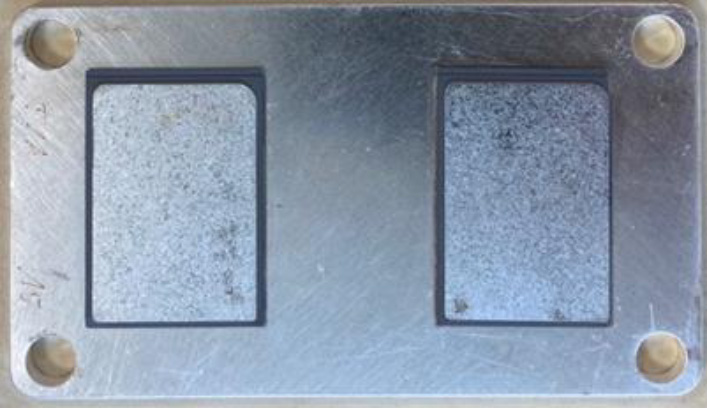
In this investigation, we evaluated the efficacy of substrate-baseplate attachment by exploring various material combinations in the baseplate, sinter paste, and substrates. The silver plated AMB and AMB2.0 substrates with copper thickness variations of 0.3 mm and 0.8 mm were obtained from Heraeus Electronics This study utilized two different sinter pastes, both optimized for large area sintering, Paste A and Paste B, produced in Hanau, as well as a reference SnAg3.5 solder paste, all of which are also manufactured by HROM. Paste A is optimized for dispensing application and Paste B is tweaked for printing process. Additionally, Aluminium (Al) and Copper (Cu) baseplates coated with silver from Metzler GmbH were tested in the project. The substrate with a copper thickness of 0.3 mm measures 38 x 27 x 0.92 mm, while the overall dimensions of the baseplate are 105.6 x 59.60 x 3 mm. Each baseplate accommodates the sintering of two substrates, as shown in the Figure 1.
B. Sintering and Soldering process
In this project, the sintering and soldering process is used to attach the substrate and baseplate. After the materials are selected, the sintering process goes through several stages, including printing the paste, convection drying, placing the substrates, and sintering. To ensure alignment with the original manufacturing standards, PINK device is utilized for sintering process. Two different sintering temperature parameters are considered in this study, while keeping all other parameters such as drying profile, pressure, and holding time as constant. Additionally, two different stencil height are employed. Each assembly is assigned with a unique short ID, and detailed information can be found in the Table 1. For greater accuracy, six samples are prepared for each combination of parameters.
| Paste | Stencil | Substrate (mm) | Baseplate | Parameter | Short ID |
|---|---|---|---|---|---|
| A | 400µm | Ag-AMB 0.3/0.38/0.3 | Ag Cu-Core | 230°C 12MPa 5 min | T1A |
| A | 400µm | Ag-AMB 0.3/0.38/0.3 | Ag Al-Core | 230°C 12MPa 5 min | T1AAL |
| A | 400µm | Ag-AMB 0.8/0.38/0.8 | Ag Cu-Core | 230°C 12MPa 5 min | T1A8 |
| A | 400µm | Ag-AMB2.0 0.8/0.38/0.8 | Ag Cu-Core | 230°C 12MPa 5 min | T1T8 |
| A | 400µm | Ag- AMB2.0 0.3/0.38/0.3 | Ag Cu-Core | 230°C 12MPa 5 min | T1T |
| A | 400µm | Ag-AMB 0.3/0.38/0.3 | Ag Cu-Core | 200°C 12MPa 5 min | T1AM |
| A | 200µm | Ag-AMB 0.3/0.38/0.3 | Ag Cu-Core | 230°C 12MPa 5 min | T1AD |
| B | 400µm | Ag-AMB 0.3/0.38/0.3 | Ag Cu-Core | 230°C 12MPa 5 min | T2RA3 |
| B | 400µm | Ag-AMB 0.3/0.38/0.3 | Ag Al-Core | 230°C 12MPa 5 min | T2Al |
| B | 400µm | Ag-AMB 0.3/0.38/0.3 | Ag Cu-Core | 200°C 12MPa 5 min | T2M |
Four Cu Baseplate samples with two Cu-AMB – 0.3/0.32/0.3 mm each were prepared with soldering process. The soldering processes 10 min of activation with formic acid at 190°C and then 260°C for 1 min and brought back to room temperature.
C. Temperature Shock Test
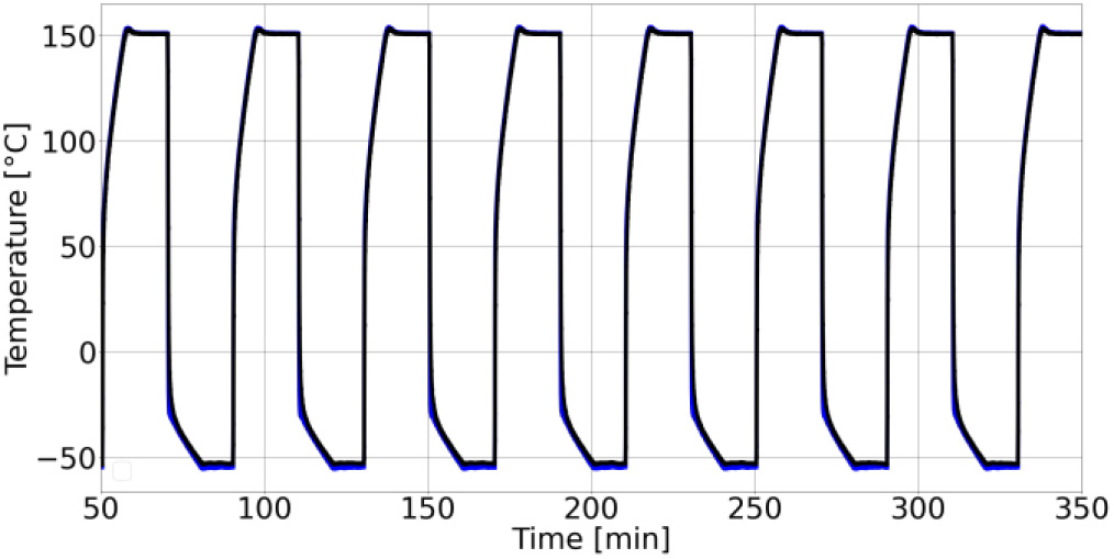
Temperature shock tests were conducted on the samples using a Vötsch 7012 S1 device containing two chambers. After conducting the preliminary test, we are confident in the samples ability to withstand higher Delta T. As a result, we have decided to simulate harsh environmental conditions, with temperature ranges from -55°C to 150°C and a cycle period of 30 minutes included in the test. K-type thermocouples are attached to the baseplates using thermal insulation material (TIM) and the initial few temperature cycles were measured using a raspberry Pi Pico logger as shown in Figure 2.
D. Scanning Acoustic Microscopy (SAM)
A non-destructive measurement method called SAM, is used to detect delamination of the sinter or solder joints. Typically, the samples are immersed in water, and an acoustic wave is directed from the transducer towards the sample, penetrating it. The resulting reflection is then recorded with time resolution by the transducer. [1] SAM images of all sintered samples are initially captured, and subsequent images are taken after each 250-cycle interval until reaching 1000 cycles, and then at every 500-cycle interval until 3000 cycles. Meanwhile, the soldered samples are subjected to SAM imaging every 50 cycles until reaching 500 cycles. Delamination is identifiable as a whitish color within a gray
background.
E. Area fraction calculation
The SAM device includes an additional feature for calculating area fraction, allowing for the determination of the total delaminated area within a specified selected area. Similar to SAM analysis, the area fraction is calculated initially and after each cycle interval of the temperature cycling tests for all samples.
F. Experimental results
The results are visualized and plotted using a Python script. For accuracy, the average area fraction of 6 samples (12 substrates) related to the same parameter is taken as a single data point, and the results are plotted for all several cycle intervals and compared with other parameter results. To gain a clearer understanding of delamination, the initial area
fraction is subtracted from the area fraction of each cycle interval. It is commonly observed that delamination initiates from the corners and increases with increasing temperature cycles. For the analysis, delamination at the sinter and baseplate is the primary focus, as it exhibits more delamination than in the vicinity of the sinter and substrate layer.
Case 1: A comparison of Paste A and Paste B reveals that both pastes exhibit similar increase in delamination with increasing temperature cycles, as depicted in Figure 3 (A). Case 2: Figure 3 (B) demonstrates that AMB2.0 and AMB display comparable results, despite differing copper thicknesses (0.3mm and 0.8mm). When delamination is compared with copper thickness, it is evident that higher thickness leads to slower degradation for both AMB and AMB2.0. Case 3: The degradation of Al baseplates is significantly higher than that of Cu baseplates, as shown in Figure 3 (D). This is attributed to the higher thermal expansion coefficient (CTE) of Al in comparison to Cu. Case 4: samples prepared with a lower sinter temperature profile experience faster delamination with increasing temperature cycles than those with a higher sinter temperature.
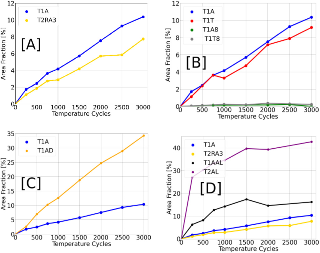
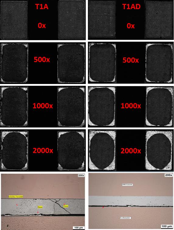
Case 5: The data from Figure 3 (C) indicates that thinner bond line thickness (BLT) results in faster delamination compared to thicker BLT. Additionally, the Figure 4 shows the delamination and crack prorogation. In cross section, it is clearly visible that T1A and T1AD have a cohesive failure of the silver sinter layer.
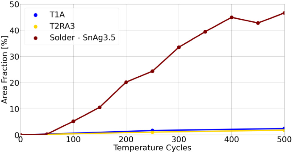
Case 6: Lastly, as depicted in Figure 5, samples prepared with solder paste exhibit significantly higher delamination as temperature cycles increase, compared to Paste A and Paste B.
III. SIMULATION
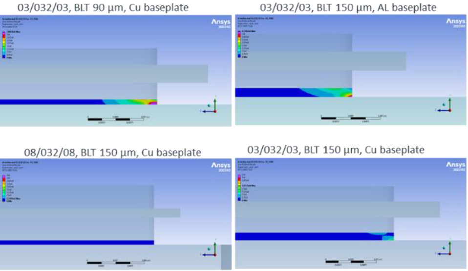
A computational model employing the finite element method (FEM), specifically the ANSYS Mechanical software, was utilized to assess thermally induced stresses within the sample. A quarter-section of the sample was geometrically simplified and discretized with a mesh for subsequent analysis Figure 6. Because of shrinkage of the paste BLT during drying and sintering the final BLT after these processes was used for modeling purposes.
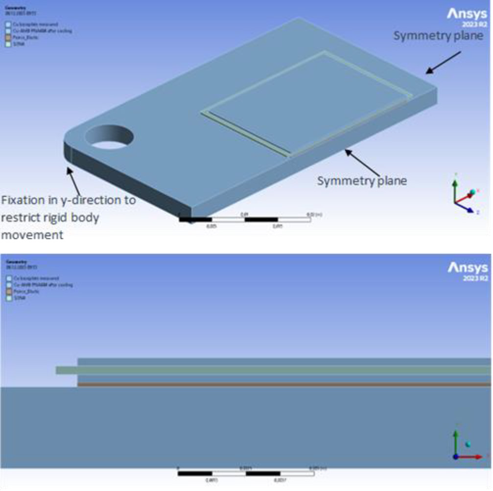
All materials—excluding ceramics—such as Cu, Al, and silver (Ag) sinter paste, were modeled to exhibit plastic deformation. A temperature-dependent viscoplastic behavioral model for the silver sinter paste, derived from tensile testing of a different paste, was applied in lieu of updated tensile data at the time of thermal TST evaluation. This approximation affords preliminary comparative insights, albeit with subsequent validation requirements. Characterization of baseplate materials incorporated tensile testing at ambient conditions, which informed the development of a rudimentary plasticity model. Essential material parameters are enumerated in Table 2. The Cu plasticity algorithm encompasses hardening phenomena attributed to thermal cycling post-brazing. Boundary conditions were configured to emulate the unconstrained movement characteristic of the TST environment. The simulation protocol aimed to replicate the transition from post-sintering cooling—from 230°C to ambient—while assuming a stress free state of the sample at 230°C, prior to TST execution.
| Material | Youngs modulus [GPa] | CTE [ppm/K] | Yield stress [MPa] | Plasticity |
|---|---|---|---|---|
| Cu baseplate | 120 | 17 | 225 | Isotropic multilinear |
| Al baseplate | 70 | 23 | 120 | Isotropic multilinear |
| Cu MCS | 120 | 17 | 55 | Isotropic multilinear |
| Si₃N₄ | 290 | 2.6 | - | - |
| Silver sinter | 26-16 [25°C-200°C] | 21 | 150 – 14 [25°C-200°C] | Voce & Pierce |
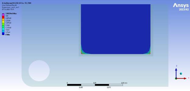
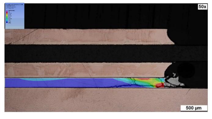
For the thermal cycling simulation, a total of five cycles were considered, predicated on the assumption of invariant temperature fields during high-low thermal transitions. Subsequent analysis concentrated on the evolution of plastic work per cycle within the sinter layer, using data from the ultimate cycle Figure 7. This metric served as a prognostic indicator for damage, which was subsequently aligned with empirical observations and integrated into a lifetime model. Damage parameter distributions demonstrated distinct alignment with failure criteria identified via SAM and cross-sectional analyses of the test samples Figure 8. Simulative iterations, corresponding to each sample variation, were executed to enhance empirical life prediction correlations. Figure 9.
IV. LIFETIME MODELING
The criterion for the experimental lifetime of the samples was established based on the onset of a 5% delaminated area. While lifetime determination for some samples was straightforward, others exhibited minimal degradation after 3000 cycles, necessitating extrapolation. For an initial approximation, we extracted the damage parameter at the maximum point located at the bottom edge of the sinter layer. Notwithstanding the influence of mesh size on this parameter’s absolute value, a consistent mesh type and size (0.5 mm) were maintained throughout this evaluation process. Nonetheless, alternate setups may require different analysis techniques, potentially involving line-based or volumetric averaging of parameters, as suggested by literature [2].
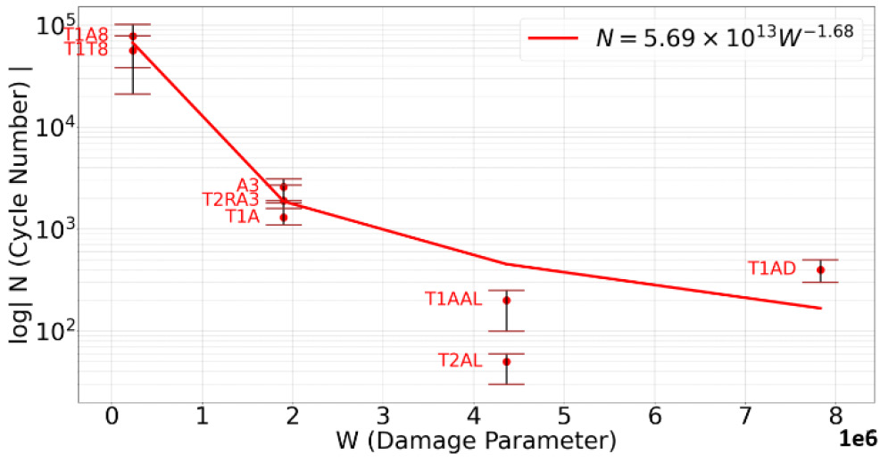
Nf = ΔWn (1)
Subsequent analysis sought to align the experimentally derived lifetimes with their corresponding peak damage parameters, employing a Morrow correlation (1), while Nf equals the lifetime in number of cycles, ΔW the change of plastic work per cycle and n as exponent. The exponent is only valid for this specific sample and is determined but a least-square fit of (1) to the experimental determined lifetimes. Preliminary observations without the aid of a fitted curve already indicated a noticeable relationship with the experimental lifetimes Figure 10. The simulations supported empirical findings, particularly noting that the usage of thicker AMB substrates correlated with extended lifetimes compared to their thinner counterparts. Furthermore, the study confirmed that BLT or the adoption of aluminum baseplates resulted in a marked lifetime reduction, evidenced through simulated outcomes.
V. CONCLUSION
The findings of this investigation affirm the potential of our novel large-area sintered silver pastes in establishing highly reliable interconnections between baseplates and metal ceramic substrates. This study evaluated our advanced substrates, AMB and its cost-effective counterpart AMB2.0, and determined that neither substrate exhibited degradation of the ceramic or its interface after enduring 3000 thermal cycles. The remarkable performance of AMB2.0 suggests comparable TST resilience as that of the standard AMB. Additionally, our observations indicated that the silver sintered attachments potentially outlast conventional SnAg3.5 soldered connections by a factor of up to 30, positioning our sintered paste as a viable selection for applications necessitating a highly reliable baseplate attachment.
Further scrutiny concluded that substrates furnished with a thicker copper layer notably enhance reliability. In contrast, diminished BLT or suboptimal sintering parameters precipitate a substantial decline in performance. The utilization of aluminum baseplates was found to be comparatively less reliable due to aluminum’s higher CTE relative to Cu. In summation, this research emphasizes that both paste-related factors—such as composition and process parameters for sintering and drying—as well as intrinsic device characteristics, including material properties and layer thicknesses, must be judiciously deliberated when transitioning from a soldered to a sintered baseplate attachment to optimize reliability where necessary.
VI. OUTLOOK
Further reliability testing will be conducted on enhanced silver sinter paste formulations to assess their applicability for large area sintering. Initial results from TST of our commercially available paste mAgic® PE360 for large sintering applications have demonstrated reduced degradation compared to the current findings. Additional research will focus on modifying sample materials and layer thicknesses to gain deeper insights into and enhance the reliability, thus investigating the impact of these parameters on the lifetime. The newly developed lifetime model will aid in the selection of pertinent samples for exploring the most promising designs. This comprehension of paste formulation and design optimization will ultimately provide a comprehensive framework for enhancing the reliability and optimizing the design of large area sintered baseplates.
REFERENCES
[1]www.heraeus.com/en/het/products_and_solutions_het/metal_ceramic_substrates/condura/condura_ultra/condura_ultra.html
[2] Wunderle et al.: “Thermo-mechanical reliability during technology
development of power chip-on-board assemblies with encapsulation”,
Microsystem technologies, Volume 15, Number 9, 1467-1478
To learn more, visit www.heraeus-electronics.com/


 with MicroForceControl (MFC)")


